Setting up a SLC 5/05 PLC
Requirements
- Allen-Bradley Edition or Ultimate Edition
- Compatible SLC 5/05 PLC with Ethernet connection
- RSLogix 500
Sample Project
This tutorial gives you step-by-step instructions on how to use a SLC 5/05 PLC to control Factory I/O.
Setting up communication between PC and PLC
-
Connect the PLC to the network.
-
Assign an IP address to the PLC.
To complete this step you should refer to the SLC 500 Modular Hardware Style User Manual, which describes methods to assign an IP address to the controller. By default, the controller is BOOTP enabled and will be assigned an IP address by a BOOTP server on the network.
-
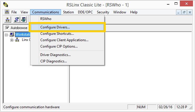
Start RSLinx and open the driver configuration dialog by selecting Communications > Configure Drivers from the menu.
-
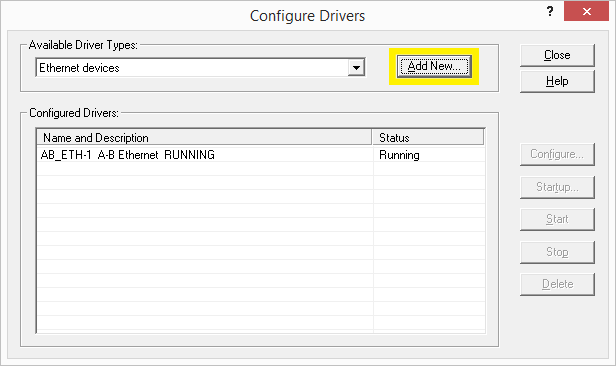
Add an Ethernet devices driver.
-
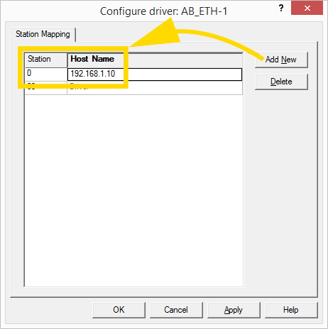
Click on Add New and enter the PLC IP address in the Host Name field.
-
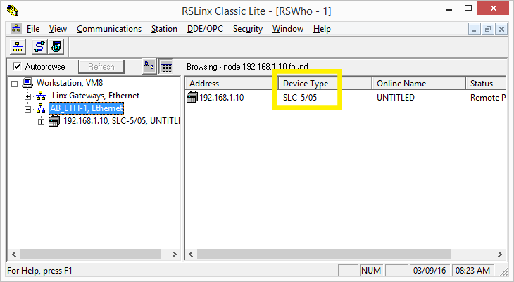
You should now be able to find the controller under the newly added driver.
Connecting Factory I/O to the PLC
-
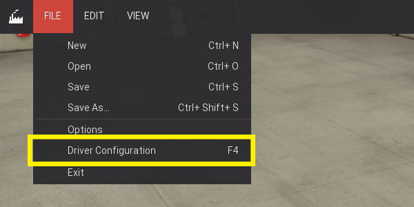
In Factory I/O click on FILE > Driver Configuration to open the Driver Window.
-
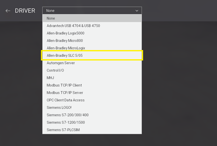
Select Allen-Bradley SLC 5/05 from the driver drop-down list.
-
Open the driver Configuration Panel by clicking on CONFIGURATION.
-
Insert the controller's IP address into the Host field.
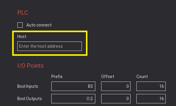
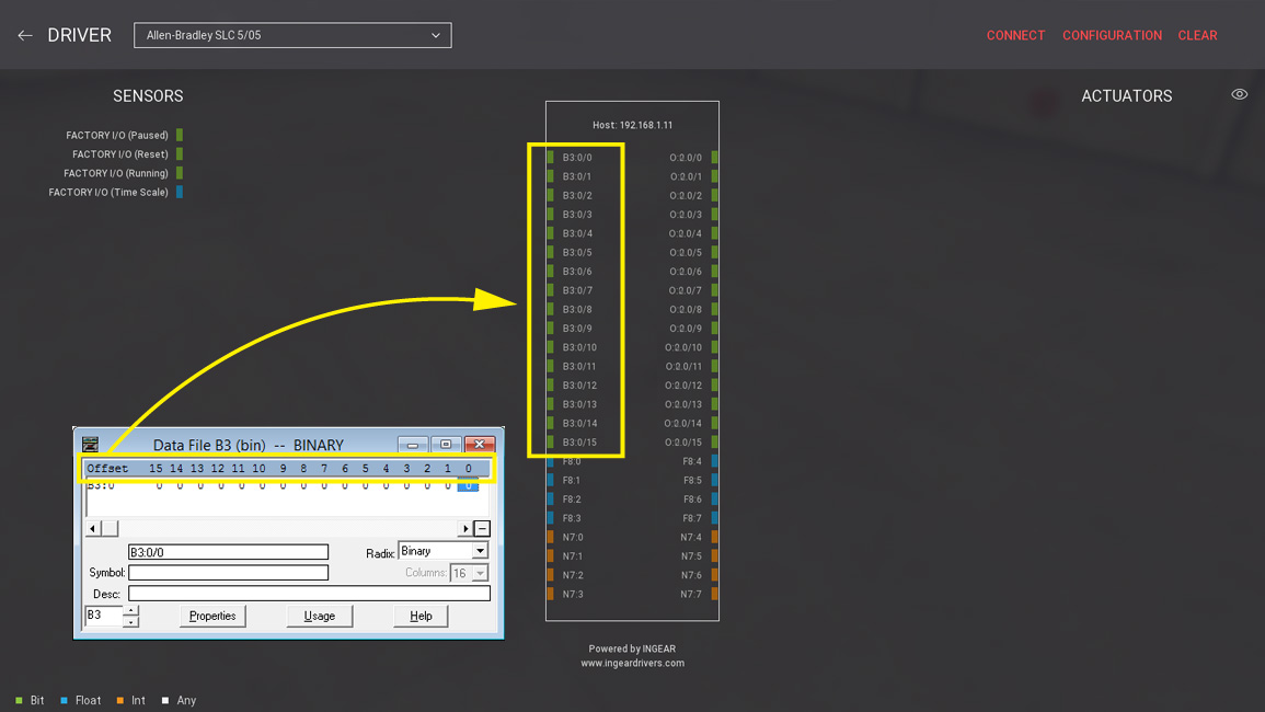
On this panel you can also define how many I/O Points to use, as well as what part of the controller's memory (tags) they reference.
Each I/O point (e.g. B3:0/0) must be associated with an element of the PLC data file. Note that you can use any data file for Bool, Float and Integer but the following rules apply:
- For Bool Inputs/Outputs, Count represents the number of bits. This means that if you would need 32 bits for Bool Inputs you would have to define, at least, 2 elements (Word) in the corresponding data file.
- For Float and Integer points, Count represents the number of elements (Word).
-
Press Esc to return to the Driver Window. Now, click on CONNECT to connect to the PLC. A successful connection is indicated by a green icon next to the selected driver, as well as next to the driver's name displayed on the status bar.
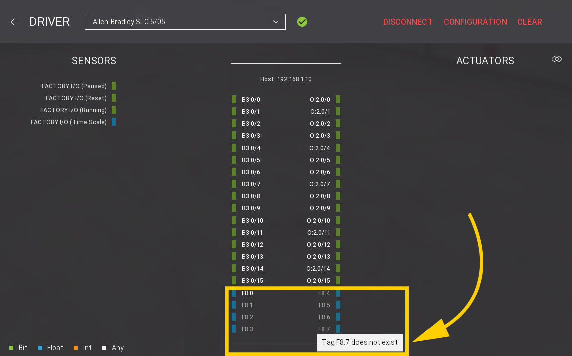
When connected to a PLC, non-existent tags or tags with an error are grayed out. Hover the mouse cursor over a grayed-out point to get relevant information about the error.
Creating Elements in RSLogix 500
-
Create a new project in RSLogix 500.
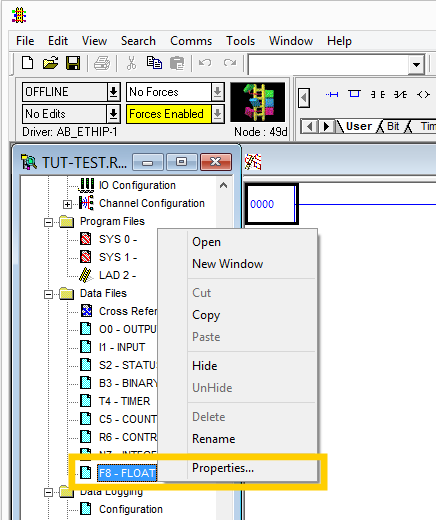
Once a new project is created, one BINARY, OUTPUT, and FLOAT elements are already defined. You must have, at least, as many elements as the ones defined in Factory I/O. Note that you are missing 7 FLOAT elements, 3 for inputs (F8:1 ... F8:3) and 4 for outputs (F8:4 and F8:7).
Note that in this example we are assuming that the PLC output card is plugged into module 2 (O:2).
-
Right-click on F8 - FLOAT data file and select Properties....
-
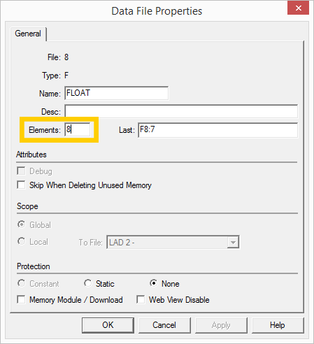
Change the number of elements to 8 and click on Apply.
-
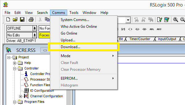
Select Comms > Download... to send the new program to the PLC.