Setting up a MicroLogix PLC
Requirements
- Allen-Bradley Edition or Ultimate Edition
- Compatible MicroLogix 1100/1400 PLC with Ethernet connection
- RSLogix 500
Sample Project
This tutorial gives you step-by-step instructions on how to use a MicroLogix 1100 PLC to control Factory I/O. These same steps apply to the MicroLogix 1400 models.
Setting up communication between PC and PLC
-
Connect the PLC to the network.
-
Assign an IP address to the PLC.
To complete this step you should refer to the MicroLogix 1100 Programmable Controllers User Manual 1763-UM001 / MicroLogix 1400 Programmable Controllers User Manual 1766-UM001, which describes methods to assign an IP address to the controller. By default, the controller is BOOTP enabled and will be assigned an IP address by a BOOTP server on the network.
-
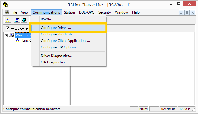
Start RSLinx and open the driver configuration dialog by selecting Communications > Configure Drivers from the menu.
-
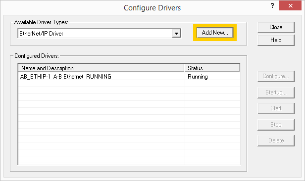
Add an EtherNet/IP driver.
-
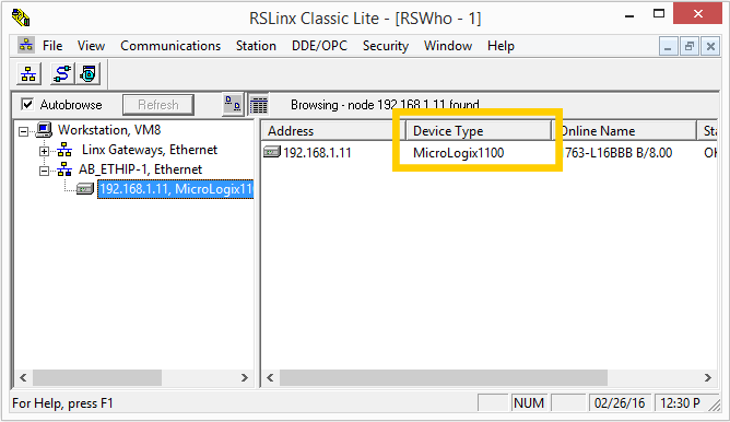
You should now be able to find the controller under the newly added driver.
Connecting Factory I/O to the PLC
-
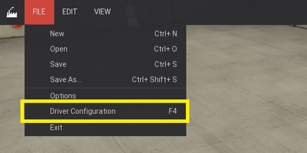
In Factory I/O click on FILE > Driver Configuration to open the Driver Window.
-
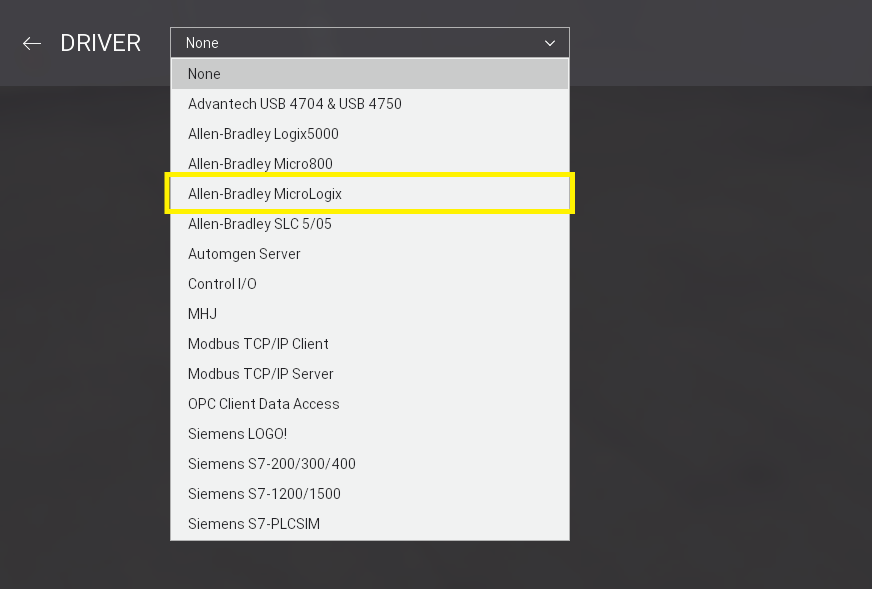
Select Allen-Bradley MicroLogix from the driver drop-down list.
-
Open the driver Configuration Panel by clicking on CONFIGURATION.
-
Make sure 1100 Ethernet is selected in the Model drop-down list and insert the controller's IP address into the Host field. If you are using a 1400 model select 1400 from the Model list instead.
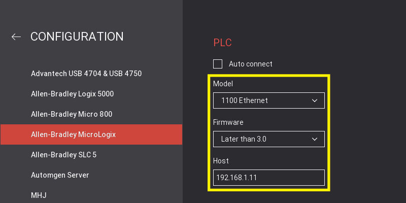
On this panel you can also define how many I/O Points to use, as well as what part of the controller's memory (tags) they reference.
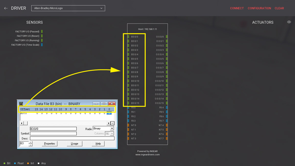
Each I/O point (e.g. B3:0/0) must be associated with an element of the PLC data file. Note that you can use any data file for Bool, Float and Integer but the following rules apply:
- For Bool Inputs/Outputs, Count represents the number of bits. This means that if you would need 32 bits for Bool Inputs you would have to define, at least, 2 elements (Word) in the corresponding data file.
- For Float and Integer points, Count represents the number of elements (Word).
-
Press Esc to return to the Driver Window. Now, click on CONNECT to connect to the PLC. A successful connection is indicated by a green icon next to the selected driver, as well as next to the driver's name displayed on the status bar.
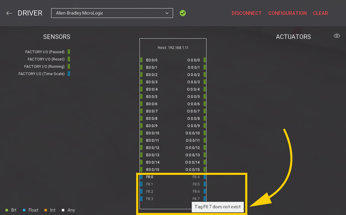
When connected to a PLC, non-existent tags or tags with an error are grayed out. Hover the mouse cursor over a grayed-out point to get relevant information about the error.
Creating Elements in RSLogix 500
-
Create a new project in RSLogix 500.
Once a new project is created, one BINARY, OUTPUT, and FLOAT elements are already defined. You must have, at least, as many elements as the ones defined in Factory I/O. Note that you are missing 7 FLOAT elements, 3 for inputs (F8:1 ... F8:3) and 4 for outputs (F8:4 and F8:7).
-
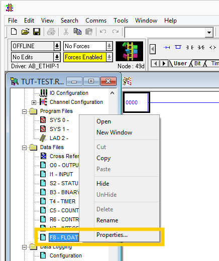
Right-click on F8 - FLOAT data file and select Properties....
-
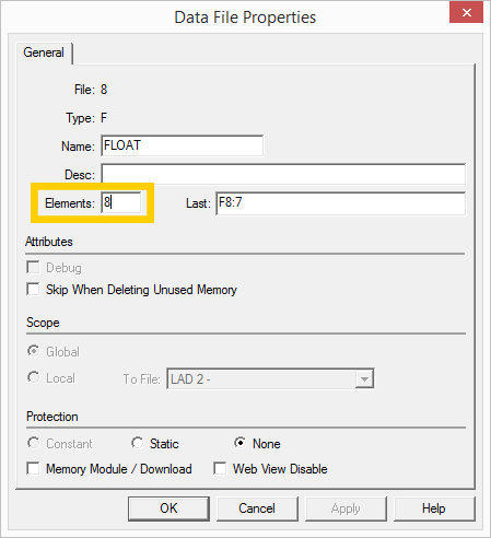
Change the number of elements to 8 and click on Apply.
-
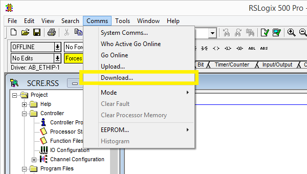
Select Comms > Download... to send the new program to the PLC.