Operators

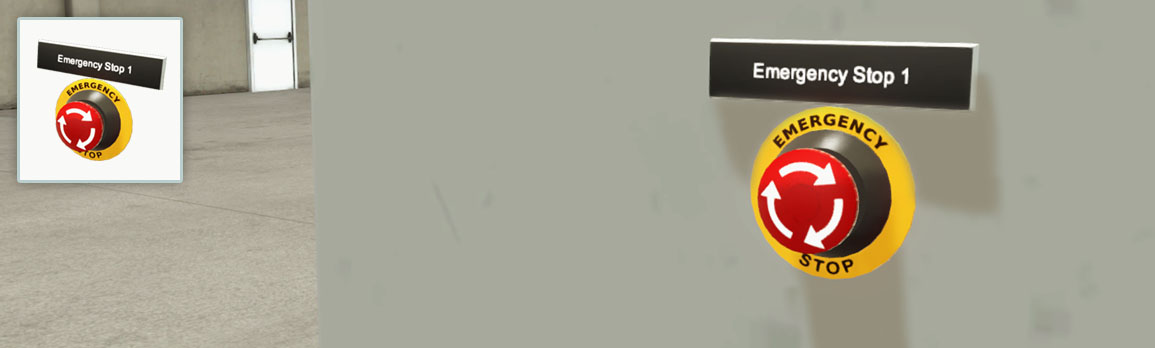
Emergency Stop
Two-position red trigger action and non-illuminated push button (mushroom head). Usually used in emergency events.
- Normally closed contact type
| Tag | Controller I/O | Type | Description |
|---|---|---|---|
| Emergency Stop # | Input | Bool | Emergency stop activated. |
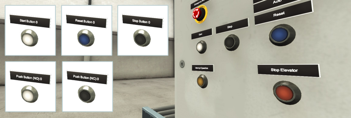
Push Buttons
Illuminated push buttons available in different colors compliant with the IEC 60204-1:2016 standard. Can be used as a momentary or alternate action, according to the selected configuration. The push button color can be changed on the context menu.
- Start, Reset, and Stop (normally closed) push buttons
- Two generic push buttons: Push Button NO (normally open) and Push Button NC (normally closed)
- Colors compliant with IEC 60204-1:2016 standard
Recommended colors by order of preference according to IEC 60204-1:2016
| Actuator | Colors | Notes |
|---|---|---|
| Start/On | White, Grey, Black or Green | |
| Reset | Blue, White, Grey or Black | |
| Stop/Off | Black, Grey or White | Red is permitted when not used near and emergency button |
| Abnormal conditions | Yellow | e.g. interruption of an automatic cycle |
Configurations
Momentary Action
| Tag | Controller I/O | Type | Description |
|---|---|---|---|
| Push Button # | Input | Bool | Pressed. |
| Push Button # (Light) | Output | Bool | Light on/off. |
Alternate Action
| Tag | Controller I/O | Type | Description |
|---|---|---|---|
| Push Button # | Input | Bool | Toggle on/off. |
| Push Button # (Light) | Output | Bool | Light on/off. |
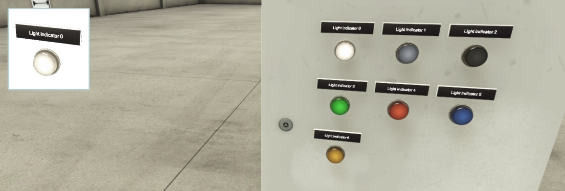
Light Indicators
Panel mount light indicator. Commonly used on instrument panels for safety applications or status indication.
- Available in different colors compliant with the IEC 60204-1:2016 standard.
| Tag | Controller I/O | Type | Description |
|---|---|---|---|
| Light Indicator # | Output | Bool | Light on/off. |
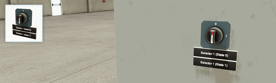
Selector
Non-illuminated selector switch mainly used to define the current state of a variable or task. Left-click and drag to toggle between states. State 0 is selected by default.
Configurations
2 Position
| Tag | Controller I/O | Type | Description |
|---|---|---|---|
| Selector # (State 0) | Input | Bool | State 0 selected. |
| Selector # (State 1) | Input | Bool | State 1 selected. |
3 Position (A)
| Tag | Controller I/O | Type | Description |
|---|---|---|---|
| Selector # (State 1) | Input | Bool | State 1 selected. |
| Selector # (State 2) | Input | Bool | State 2 selected. |
3 Position (B)
| Tag | Controller I/O | Type | Description |
|---|---|---|---|
| Selector # (State 1) | Input | Bool | State 1 selected. |
| Selector # (State 2) | Input | Bool | State 2 selected. |
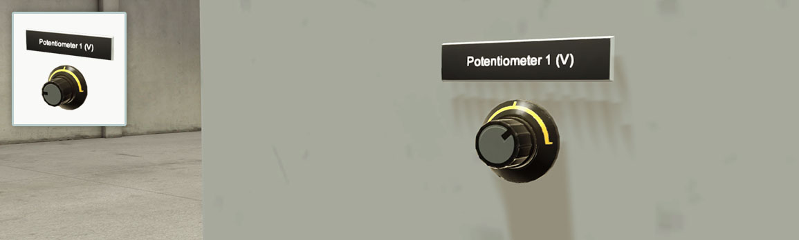
Potentiometer
Used to generate an analog value proportional to the knob rotation. The selected configuration can define the value range.
Configurations
[0, 10] V
| Tag | Controller I/O | Type | Description |
|---|---|---|---|
| Potentiometer # (V) | Input | Float | Current value. |
[-10, 10] V
| Tag | Controller I/O | Type | Description |
|---|---|---|---|
| Potentiometer # (V) | Input | Float | Current value. |
[-5, 5] V
| Tag | Controller I/O | Type | Description |
|---|---|---|---|
| Potentiometer # (V) | Input | Float | Current value. |
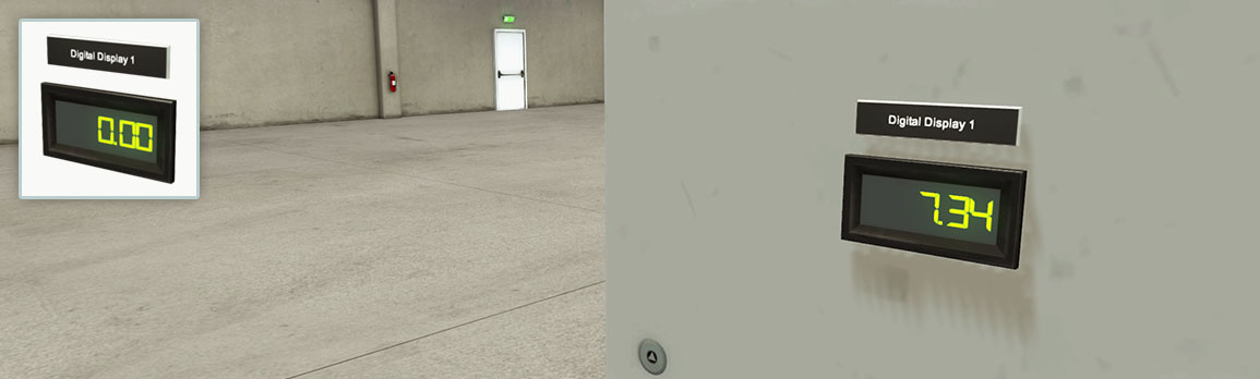
Digital Display
Allows numerical values to be displayed during the simulation. The selected configuration defines the value range and data type.
Configurations
[0, 10] V
| Tag | Controller I/O | Type | Description |
|---|---|---|---|
| Digital Display # | Output | Float | Displays value. |
[-10, 10] V
| Tag | Controller I/O | Type | Description |
|---|---|---|---|
| Digital Display # | Output | Float | Displays value. |
Integer
| Tag | Controller I/O | Type | Description |
|---|---|---|---|
| Digital Display # | Output | Integer | Displays value. |
BCD
| Tag | Controller I/O | Type | Description |
|---|---|---|---|
| Digital Display # | Output | Unsigned packed BCD | Displays value. |
Hexadecimal
| Tag | Controller I/O | Type | Description |
|---|---|---|---|
| Digital Display # | Output | Hexadecimal | Displays value. |
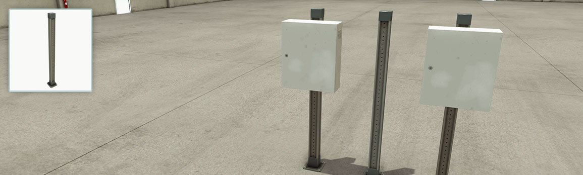
Electric Switchboard
Used to design an electric board with operators.
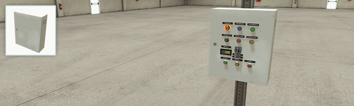
Column
Metal structure typically used to hold an electric switchboard.