Siemens S7-PLCSIM
Requirements
- Siemens Edition or Ultimate Edition
- Siemens S7-PLCSIM V5/13-18/Advanced v3.0
Tutorials:
- Setting up S7-PLCSIM V5
- Setting up S7-PLCSIM V13-18
- Setting up S7-PLCSIM Advanced V3.0
- Setting up S7-PLCSIM Advanced V4.0
Samples:
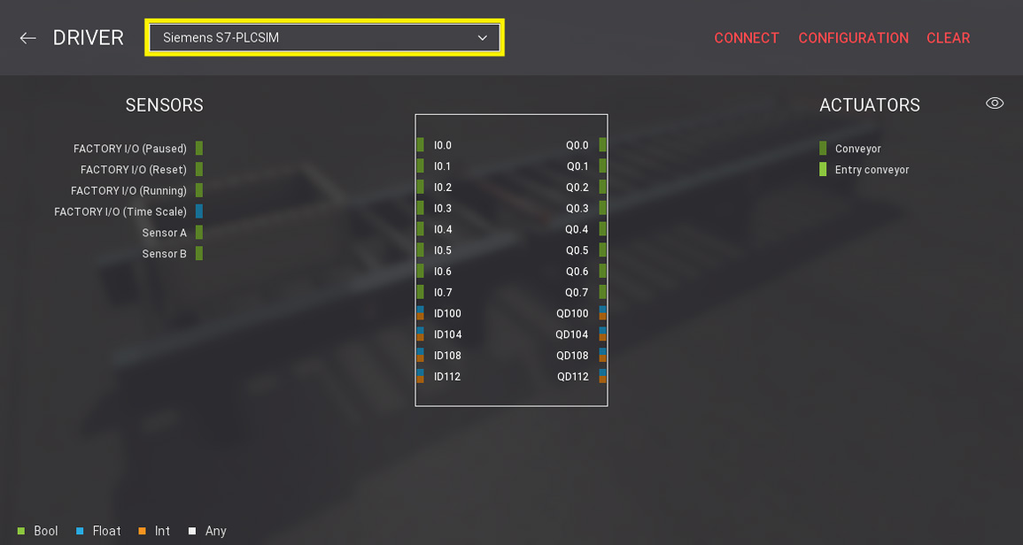
This driver provides connectivity with Siemens S7-PLCSIM. It can be used to control Factory I/O with S7-PLCSIM v5/13-16/Advanced through TIA Portal.
TIA Portal Template Projects
Note that you must use a TIA Portal template project when connecting with S7-PLCSIM v13-18. Without these templates, Factory I/O will not be able to communicate with this particular version of S7-PLCSIM.
Configuration
| Configuration Setting | Description |
|---|---|
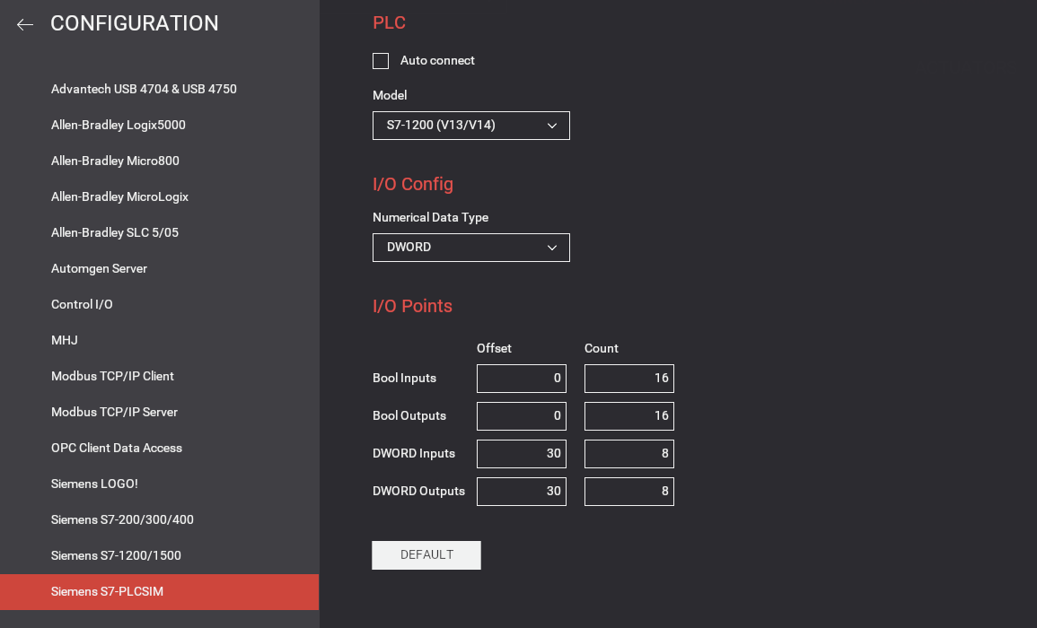
| Auto connect | Periodically tries to connect to the PLC until a successful connection is established. |
| Model | PLC model: S7-300, S7-1200, S7-1500 or S7-1500 (S7-PLCSIM Advanced). S7-PLCSIM Advanced must be configured with an instance name set to factoryio. You can change the instance name with the console command drivers.siemens_s7plcsim.instance_name = 'newname'. |
| Numerical Data Type | Choose whether WORD or DWORD will be used for analog values. |
| Bool Inputs | Address offset and number of Bool inputs to use for digital sensors (max 256). Sensors' values are written into I memories starting at address 0 (by default). |
| Bool Outputs | Address offset and number of Bool outputs to use for digital actuators (max 256). Actuators' values are read from Q memories starting at address 0 (by default). |
| DWORD Inputs | Address offset and number of DWORD/WORD inputs to use for analog sensors (max 64). |
| DWORD Outputs | Address offset and number of DWORD/WORD outputs to use for analog actuators (max 64). |
| Default | Click to reset to the default options. |
About Analog Values
You should be aware of how floating and integer values are exchanged between Factory I/O and the PLC. The driver can be configured to read/write values using WORD or DWORD and the following list gives you detailed information on how data is encoded/decoded in both cases.
DWORD Inputs (Sensors)
- Floating sensor values are encoded as 32-bit floating point numbers (REAL).
- Integer sensor values are encoded as 32-bit integers.
DWORD Outputs (Actuators)
- Floating actuator values are expected as 32-bit floating point numbers (REAL).
- Integer actuator values are expected as 32-bit integers.
WORD Inputs (Sensors)
- Floating sensor values ranging from -10 V to 10 V are linearized between -27648 and 27648.
- Floating sensor values ranging from 0 V to 10 V are linearized between 0 and 27648.
- Integer sensor values are converted into signed 16-bit integers.
WORD Outputs (Actuators)
- Floating actuator values ranging from -10 V to 10 V are expected to be linearized between -27648 and 27648.
- Floating actuator values ranging from 0 V to 10 V are expected to be linearized between 0 and 27648.
- Integer actuator values are expected as signed 16-bit integers.
When using WORD, conversion between integer values and real number values can be done with the 'SCALE_X' and 'NORM_X' instructions.
TIA Portal Template Projects
In the existing OB1 there is already a Network 1
Do not delete this network. Otherwise, the connection will not work.
Downloads for TIA Portal v13
FactoryIO_Template_S7-1200_V13.zip
FactoryIO_Template_S7-1500_V13.zip
Downloads for TIA Portal 14
FactoryIO_Template_S7-1200_V14.zip
FactoryIO_Template_S7-1500_V14.zip
Downloads for TIA Portal 15 / 16
FactoryIO_Template_S7-1200_V15.zip
FactoryIO_Template_S7-1500_V15.zip