Getting Started
This getting started guide will walk you through the basics of CONTROL I/O. You will learn about the graphical user interface, available blocks and how to create a simple diagram.
User Interface
If you are new to CONTROL I/O, it will be useful to get an introduction to a few basic concepts regarding the user interface.
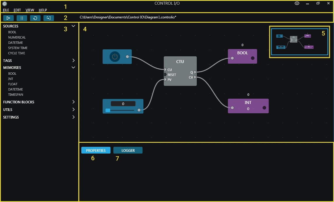
| Section | Description |
|---|---|
| 1. File Menu | Gives access to general commands. |
| 2. Toolbar | Controls the diagram execution. Use it to start, pause, reset, or perform a single diagram update step. By default toolbar buttons also control FACTORY I/O. You can disable this functionality in the settings tag. |
| 3. Blocks Palette | List of all blocks grouped by type. You will also find the application settings here. |
| 4. Canvas | Where the function block diagram is drawn. |
| 5. Canvas Overview | Gives a visual representation of the entire diagram. |
| 6. Properties | Displays properties and relevant information of selected blocks. |
| 7. Logger | Displays useful information about the application execution. |
Blocks
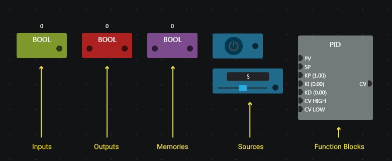
A block represents a value (Boolean, Integer, Float ...) or a function between inputs and outputs (Counter, Timer, ...). Blocks are made of sockets used to link different blocks together. By linking blocks together, you define how data flows from the most upstream to the most downstream block (left to right). Output sockets can only be linked to input sockets; you cannot create feedback by linking output sockets to input sockets directly. To create loops in your diagrams, you will have to use memories, more on this later.
| Block Type | Description |
|---|---|
| Sources | Blocks used to generate data. You will find a different block for each data type supported and also blocks providing system time and cycle time. |
| Tags | I/O points available in FACTORY I/O (sensor and actuator tags). These are automatically detected by CONTROL I/O. |
| Memories | Used to story values during the execution of the program. |
| Function Blocks | Function blocks describing a function between inputs and outputs. Can be logical, arithmetic, timers, counters... |
Designing Your First Controller
The focus of this Getting Started guide is to walk you through the basics of working with CONTROL I/O. The best way to achieve our goal is to start designing a controller for a FACTORY I/O scene.
-
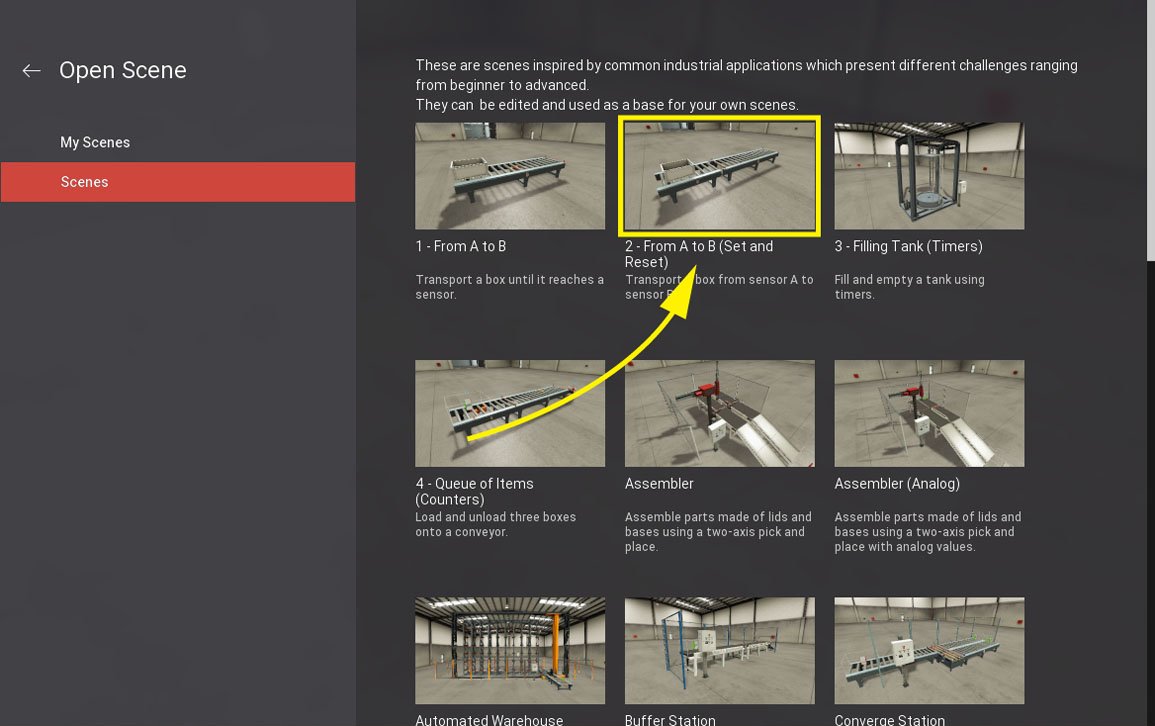
Start FACTORY I/O and open the scene "From A To B (Set and Reset)".
-
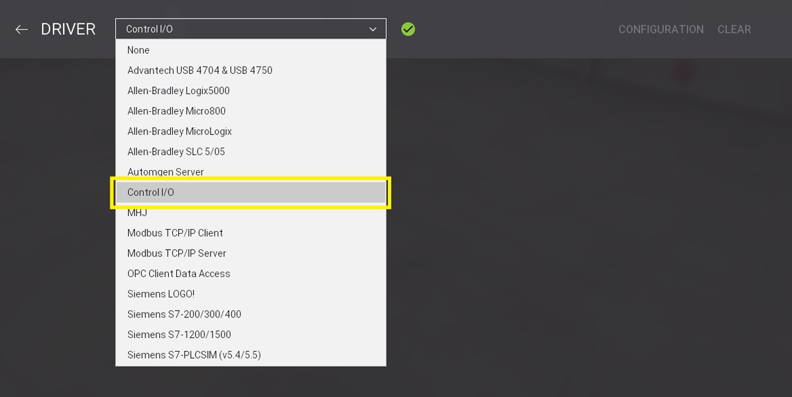
Click on File > Drivers (F4) and choose Control I/O from the Driver list. CONTROL I/O will be automatically launched.
-
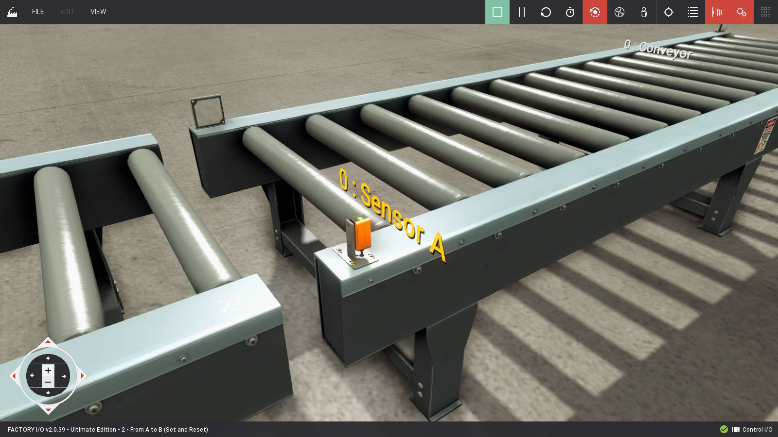
The goal of this scene is to transport a box from Sensor A until it reaches Sensor B. It is a very simple scene which makes it ideal to start with. Some important remarks:
- The entry conveyor is always On (forced)
- Sensor A and Sensor B are retro-reflective sensors which have normally closed signals. This means that when nothing is being detected the sensor value is True.
-
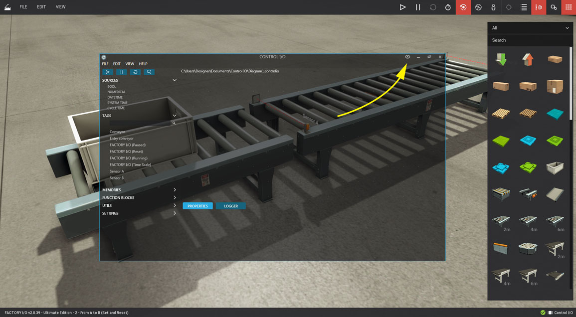
Switch to CONTROL I/O. If you are using a single display you can make CONTROL I/O transparent by clicking on the eye icon, which allows you to see FACTORY I/O and the diagram at the same time.
-
Now, let's start describing what our controller is supposed to do:
- Once a box is detected by Sensor A it must switch the Conveyor On
- Once a box is detected by Sensor B it must switch the Conveyor Off
- Keep in mind that Sensor A and Sensor B have normally closed signals
-
Our controller is very simple; we will set a memory to True once Sensor A detects a box and switch it to False once Sensor B detects it again.
-
You will find scene tags on the Tags panel. Note that any change made to scene tags is reflected automatically on CONTROL I/O.
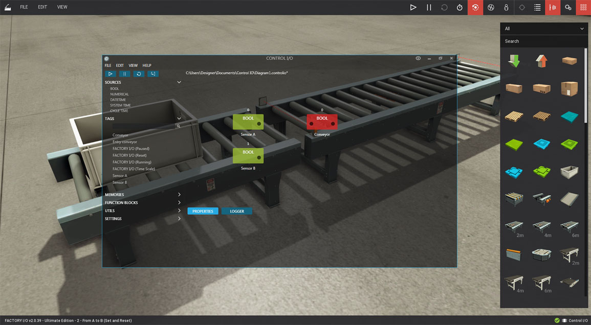
Let's start by dragging Sensor A, Sensor B and Conveyor tags into the canvas. You will notice that Sensor A and B are green blocks which indicate they represent inputs (sensors). On the other hand, Conveyor is red and represents an output (actuator).
-
Since Sensor A and Sensor B have normally closed signals we need to complement them by using an NOT block. Expand the Function Blocks > Logical tab and drag two NOT blocks into the canvas. Now, link to each sensor block by Left-clicking and Dragging from the output socket to the input socket. From now on, when each sensor detects a box we will get a True value.
-
When sensor A detects a box, we must memorize it. For that, we will use a function block called SR. This block represents a memory which can be set and reset if it's set and reset at the same time it will give priority to set (an RS block gives priority to reset). Drag an SR block into the canvas and link Sensor A signal to Set1 and Sensor B to Reset. Finally, link the SR output to the Conveyor block.
-
At this point, you should save your work by selecting Save from the File Menu.
-
On the toolbar, click on Run. CONTROL I/O will start executing the diagram and switch FACTORY I/O to Run mode. At any moment, you can stop, pause and reset the diagram execution.